Company:Lanjingxin Microelectronics Co., Ltd.
Hotline:+86-0755-27383055-20
Email:sales@lucki.com.cn
Address: 6th Floor, Building 43A, Baotian Industrial Zone, Qianjin 2nd Road, Baoan District, Shenzhen

1. Quartz crystal and frequency control components
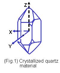
Quartz is a combination of silicon and oxygen atoms of silicon dioxide (Silicon Dioxide, SiO2), a single crystal structure formed by a 32-point group of hexagonal crystal system (Figure 1). The single crystal quartz crystal structure has a piezoelectric effect Characteristic, when pressure is applied in certain directions of the crystal, an electrical potential will be generated in the direction of the vertical force. On the contrary, when an electric field is applied to certain axial directions of the quartz crystal, deformation or vibration will occur in other directions Mastering this piezoelectric effect of single crystal quartz material, using its characteristics of resonant frequency, and using its accuracy as a reference for various types of frequency signals, is the design and application of crystal oscillators. Because quartz crystals have very high Material Q value, so most frequency control components, such as resonators and oscillators, are based on quartz materials. Quartz-based frequency control components can be divided into bulk waves according to their piezoelectric vibration properties (bulk wave) vibration components and surface acoustic wave vibration components. Bulk wave vibration components such as quartz crystal resonators, quartz crystal filters and quartz crystal oscillators, surface wave vibration components such as surface wave filters and surfaces Wave resonator. When the quartz crystal is ground in a specific cutting method and mechanically processed to complete a specific external size, it is called a quartz chip (quartz wafer or quartz blank). Place the quartz chip in a vacuum environment , After plating electrodes on the surface, fixing them on a metal or ceramic base with conductive materials, and encapsulating them, it becomes a so-called quartz crystal resonator (quartz crystal resonator). Impedance characteristics and wave overlapping characteristics, with adjacent double electrodes, you can make a quartz crystal filter. Adding different electronic oscillation circuits to a quartz oscillator can make a quartz oscillator with different characteristics. For example: quartz frequency oscillation (CXO), Voltage Controlled Crystal Oscillator (VCXO), Temperature Compensated Crystal Oscillator (TCXO), Oven Controlled Crystal Oscillator (OCXO) …Etc. The resonance of the bulk wave is the resonance of the surface acoustic wave. The surface oscillation wave generated by the inter-digital-transducer (IDT) method on the surface of the quartz crystal can be produced with a short wavelength (high frequency) Resonant surface acoustic wave resonator (SAW Resonator) or surface acoustic wave filter ( SAW Filter).

Fourth, the vibration mode of quartz crystal
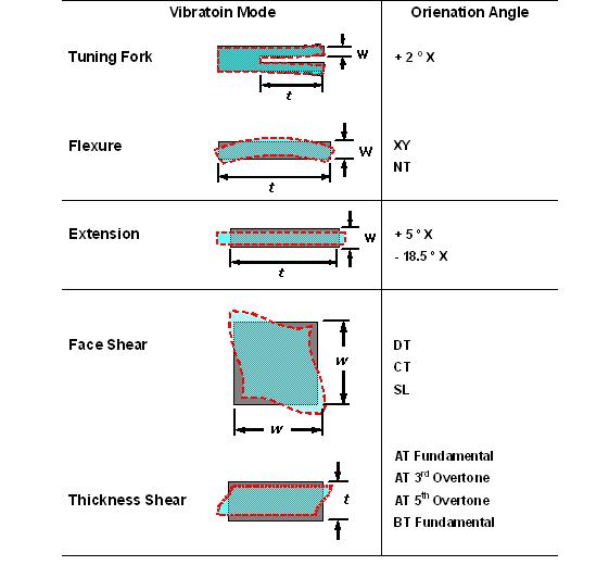
Through different quartz cutting angles and the electric field effect of different electrode shapes, the quartz chip exhibits a variety of different vibration modes. Frequently generated vibration modes can be roughly divided into flexure mode and stretch mode (extension mode), face shear mode (face shear mode) and thickness shear mode (thickness shear mode). These vibration modes can be seen in Table 1 in a simple way. In actual conditions, A quartz chip does not necessarily have a single vibration mode, but there may be multiple modes in the oscillation of a quartz chip at the same time. With proper design, other undesired vibration modes (unwanted modes) can be suppressed. Achieve the optimization of the main vibration modes.
5. Frequency and temperature characteristics of quartz crystals
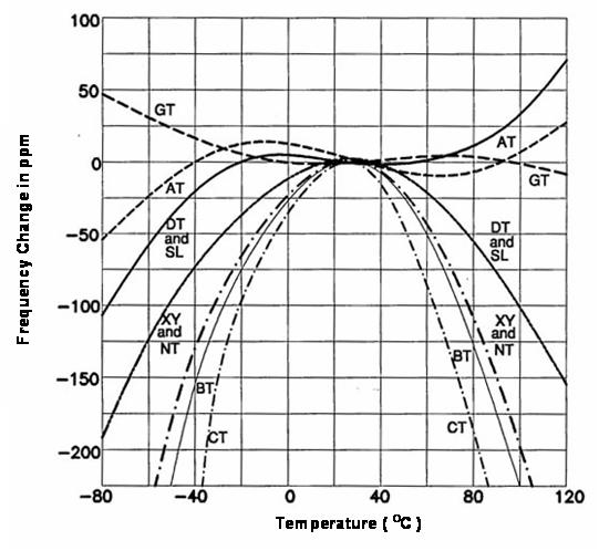
Most quartz crystal products are used as reference frequency reference or frequency control components on electronic circuits. Therefore, the characteristics of frequency and working environment temperature are a very important parameter. In fact, good frequency and temperature (frequeny versus temperature) )Characteristics are also one of the main factors for choosing quartz as frequency components. With proper definition and design, quartz crystal components can easily meet the frequency error of parts per million (ppm). Scope. If LCR parts are formed into a high-frequency oscillation circuit in a discrete circuit method, although the required reference frequency signal error can be achieved in a small-scale production scale at ppm or sub-ppm level requirements, this method cannot meet the requirements of the industry. The scale of mass production. The frequency-to-temperature characteristics of quartz components are even more difficult to achieve with discrete oscillation circuits. In (Figure 4), several frequency-to-temperature characteristic curves of different quartz crystal cutting angles are provided.
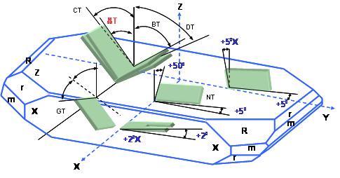
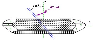
Among the different types of cutting angle methods, AT angle cutting quartz chips are suitable for the frequency range of several MHz to hundreds of MHz. It is the most widely used and most used cutting application method for quartz chips. In ( In Figure 5), from the upper view of the X-axis of the quartz crystal rod, you can see the AT direction that rotates about 35 degrees to the Z-axis. This is also a very good way of working in mass production technology.
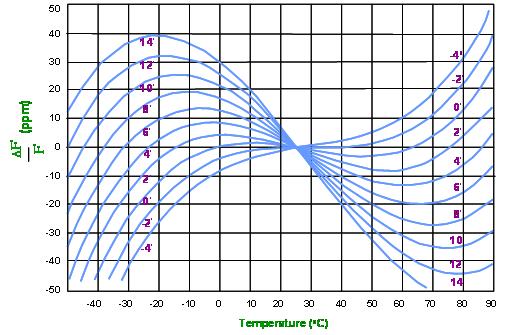
(Figure 6) is an expanded view of the frequency vs. temperature characteristics of the AT cutting angle change in the thickness vibration mode. In the figure, the commonly used room temperature camera is 25 degrees as the relative zero point. The biggest advantage of AT cutting is that the frequency changes to temperature as one yuan Cubic curve. This characteristic can be seen from (Figure 6). In a fairly wide temperature range, the first and second order constants of the temperature curve of AT cutting are zero, and the third order constant determines The change value of frequency versus temperature.,
six. Equivalent circuit and parameters of quartz crystal resonator
(Figure 7) (a) and (b) are the basic structure diagrams of the DIP type and SMD type quartz resonator respectively. (Figure 7) (c) is the electronic symbol used on the electronic circuit to represent the quartz resonator. When quartz When the crystal resonator is far away from the oscillation frequency region, the quartz crystal resonator is only a capacitive component.When the frequency is close to the oscillation frequency of the quartz crystal, it is close to an inductive equivalent LCR oscillation circuit.

(Figure 8) It is to convert the quartz crystal resonator into a Butterworth-Van Dyke (BVD) equivalent circuit near the oscillation frequency. In this figure, there are four main parameters: static capacitance-Co, dynamic capacitance-C1, dynamic inductance -L1 and dynamic resistance -R1.


Seven. Resonance Frequency (Resonance Frequency)
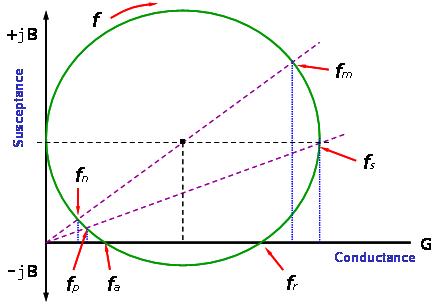
In technical literature and product applications, the resonance of a quartz crystal resonator has three sets of resonance frequencies with different definitions and characteristics.
(1) Series resonance frequency and parallel resonance frequency (fs, fp)
(series resonance frequency and parallel resonance frequency)
(2) Resonant frequency and anti-resonant frequency (fr, fa)
(resonance frequency and anti-resonance frequency)
(3) Maximum conductance frequency and minimum conductance frequency (fm, fn)
(maximum admittance frequency minimum admittance frequency).
The admittance diagrams of these three sets of frequencies can be clearly seen from the complex coordinates (Figure 9)
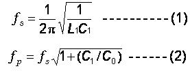
C1 and L1 in the formula are the dynamic capacitance (motional capacitance) and dynamic inductance (motional conductance) in (Figure 7) respectively; Co is the static capacitance (shunt capacitance).
8. Proprietary Names
(1) Nominal Frequency and Tolerance
Under the correct oscillation circuit matching, the frequency output from the oscillation circuit is called "nominal frequency (nominal frequency)". The frequency unit is generally expressed in megahertz (MHz, MHz) or kilohertz (Kilohertz, KHz).
In actual mass production and oscillation circuit applications, the product will have some frequency dispersion error relative to the center frequency in a room temperature environment (25oC). The maximum dispersion value of this type of frequency tolerance is generally ppm (parts per million) Or% (percent) to indicate.
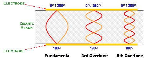
(2) Fundamental and Overtone Vibrations Mode
The quartz crystal resonator at the AT cutting angle mainly exists in the thickness shear oscillation mode. When the quartz crystal resonates, in addition to the fundamental wave oscillation, the high-order frequency double resonance also exists in the quartz crystal at the same time as the fundamental wave oscillation. Between the electrode areas. However, because the piezoelectric material electrodes are in a vibration environment with opposite electrical phases, only odd number multiples (odd number) high-frequency doubles can occur, and even number multiples (even number) double-frequency resonance occurs in quartz Crystal resonators will not exist (Figure 10).
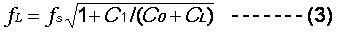
(3) Load Capacitance (CL)
The “load capacitance” on the oscillation circuit is defined as: all the capacitance values encountered by the oscillation circuit from the two terminals of the quartz crystal resonator. The load capacitance can be connected in parallel with the quartz crystal resonator on the circuit. ) Or connected in series (series). In the oscillation circuit connected in parallel, the size of the load capacitance (CL) will affect the characteristics of the nominal frequency.
The resonance frequency of this load capacitor parallel circuit is expressed by fL:
(4) Frequency-Temperature Stability
The frequency of quartz changes due to temperature changes. This is due to the different thermal expansion coefficients of the quartz material in each coordinate axis. When the temperature changes, the lattice distance of each axis changes slightly. When different cutting angles are used, different oscillations The modal changes will also be different.
In the design of the thickness-shear oscillation mode at the AT cutting angle, the frequency of 25 degrees Celsius is generally used as the reference temperature point to define the stability of frequency changes within the working environment temperature range. In defining this frequency to temperature stability At the same time as the parameters, the corresponding operating temperature range (Operation Temperature Range) should also be specified together.
The characteristics of quartz frequency component frequency versus temperature stability, like the nominal frequency error, are measured in ppm or %. The frequency-temperature characteristic curve of the component and the quartz cutting angle, oscillation mode, surface treatment and appearance Size has a great relationship. In addition, the characteristics of the load capacitance (CL) and drive level on the oscillation circuit will also affect the stability of the oscillation circuit's output frequency to temperature changes.
(5) Equivalent Series Resistance (ESR)
When the quartz crystal oscillates in series at fs, C1 and L1 are in opposite phases and cancel each other. The admittance of the motional arm of the entire resonator is close to the minimum impedance value R1. At this time, the entire quartz crystal resonator The performance is only a resistive component. The resistance value R1 is the mechanical energy loss of the entire component. It includes the quartz material, followed by all the energy loss on the material and the packaging material.
(6) Dynamic Capacitance (Motional Capacitance C1) and Dynamic Inductance (Motional Inductance L1)
In formula 1, the dynamic capacitance C1 and the dynamic inductance L1 are related to the series resonance frequency, fs.
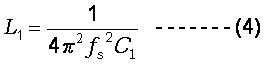
In the actual measurement system, we can only measure the dynamic capacitance C1 and the series resonance frequency fs. The dynamic inductance L1 is calculated by formula (4).
(7) Static Capacitance or Shunt Capacitance, Co
The static capacitance, Co, mainly comes from the capacitance formed by the quartz chip as a dielectric material and two electrodes; another small part of the static capacitance comes from the capacitance and package between the conductive adhesive material connecting the quartz chip and the wiring The capacitance of the case.
The static capacitance is measured in a range far below the oscillation frequency to avoid being affected by the dynamic capacitance near the oscillation frequency. Equation (5) is the mathematical expression of the static capacitance.

In formula (5), A represents the area of the electrode; d represents the thickness of the quartz chip; ε is the corresponding dielectric value of the quartz chip; Cm+p is the capacitance value generated by other materials.
(8) Drive power (Drive Level)
The driving power of a quartz crystal refers to the power consumption of the quartz crystal resonator. It is generally expressed in microwatts. The design of the oscillation circuit must provide an appropriate power for the quartz crystal resonator to start and maintain the oscillation. For the quartz crystal Oscillation is a physical high-frequency mechanical vibration, and the electrical impedance value during oscillation is about 10-100 ohms or less (depending on the frequency range and size). If the oscillation circuit provides too high driving power, it will cause the quartz crystal The non-linear characteristics of the change and the deterioration of the quartz/electrode/adhesive material interface will cause excessive changes in the oscillation frequency FL and equivalent impedance R1. Quartz crystals will be unstable if they work under excessively high driving power for a long period of time. With the low power consumption requirements of various applications and the trend of product miniaturization, coupled with the substantial improvement in the technology of quartz products in recent years, the electrical impedance value of the quartz crystal resonator has decreased and stabilized as a whole. The design of the oscillation circuit is not required, It should not provide too high driving energy on the quartz crystal resonator. For most applications, the oscillation circuit provides a maximum power of 10 ~ 100 microwatts (depending on the size and frequency of the quartz resonator). It may be enough for the quartz resonator.
(9) Electrical Quality Factor (Q)
For a quartz crystal resonator, the electrical quality factor Q is a very important characteristic. The electrical quality factor can be expressed by the following formula (6)
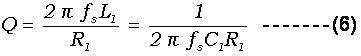
The quality factor of the resonator of a quartz crystal can reach several million or more.
(10) Pullability (Pullability) and Sensitivity (Trim Sensitivity)
Quartz crystal resonators are used in parallel oscillation circuits, and the oscillation frequency has a great relationship with the load capacitance CL. This can be seen in the previous formula (3). (Figure 11) is based on the FL frequency on the parallel oscillation circuit Schematic diagram of the change curve of the load capacitance CL.
The frequency "pulling rate" refers to the frequency change from the frequency FL1 of the load capacitance CL1 to the frequency FL2 of the load capacitance CL2. In (Figure 11) it can be the frequency of FL1 (CL=24pF) and FL2 (CL=10pF) Change value. In this example, the frequency pulling rate is 220 ppm. If we minimize the load capacitance values of CL1 and CL2 (the curve is mathematically differentiated), we will get the tangent value of the curve. This tangent value It is to use the trim sensitivity of a certain load capacitance.
In (Figure 11), the frequency sensitivity at CL=24 pF is 10 ppm/pF, and the frequency sensitivity at CL=10 pF is 20 ppm/pF. In parallel lines, the smaller the load capacitance, the frequency The higher the sensitivity to load capacitance changes. On the contrary, the larger the load capacitance, the lower the frequency sensitivity to load capacitance changes. This is when the quartz crystal resonator is used on the VCXO circuit, the circuit design will choose a smaller load Capacitance. On the contrary, when a more accurate frequency signal is required, a higher load capacitance will be selected in the circuit design.

(11) Aging (AGING)
"Aging", as the name implies, refers to the frequency change of a quartz crystal resonator over time within a certain period of time, expressed in parts per million (ppm). Aging is in terms of frequency and time. The characteristic curve generally shows an exponential type of change. The period of maximum frequency aging change is the first month after the quartz frequency component is made. After that, the frequency change gradually decreases with time. Frequency aging characteristics There are several main factors affecting. For example, the packaging method, the type of material, the process temperature, the process control, the heat treatment process and the size and frequency of the product. Most of the specifications have to define the short-term (1~3 months) ) Or long-term (1-10 years) frequency aging requirements.
(12) Storage temperature range (STORAGE TEMPERATURE RANGE)
In addition to the previous working environment temperature range, another temperature-related feature is the "Storage Temperature Range". This parameter refers to the highest and lowest temperature range that the product can be stored under static conditions. In this temperature range, the product must ensure that after a long period of storage, it can still work within the working temperature range and meet the specifications. This feature has a lot to do with the component design and process design of the quartz crystal resonator. Be careful with the definition.
(13) Negative Resistance (-R)
Negative impedance refers to the impedance characteristic value of the oscillation line encountered at the oscillation frequency when viewed from the two terminals of the quartz crystal resonator to the oscillation line. The oscillation line must provide sufficient amplification gain to compensate for the quartz crystal resonator The mechanical energy loss at resonance. Negative impedance is not a product parameter of the quartz resonator, but it is an important characteristic parameter of the oscillation circuit. From the perspective of the resonator, it is the "negative impedance" of the oscillation circuit.
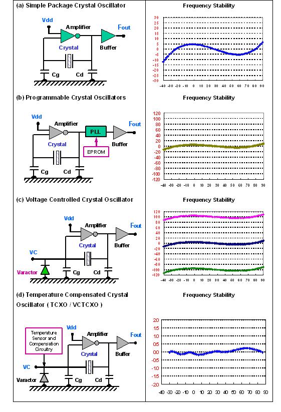
9. Quartz crystal oscillator (CRYSTAL OSCILLATORS)
When the quartz resonator is integrated with the oscillation circuit or integrated circuit (IC) in a package, the power supply voltage is provided from the outside to form an active component output frequency signal, which is the so-called quartz crystal oscillator. The quartz crystal oscillator can be used by Different oscillation circuits and output circuits inside a single package component provide reference frequencies with different characteristics. For example, there is a quartz frequency oscillator SPXO (Simple Package Crystal Oscillator) or CXO (Clock Crystal Oscillator), which can be programmed PCXO (Programmable Crystal Oscillator), Voltage Controlled Crystal Oscillator VCXO (Voltage Controlled Crystal Oscillator), Temperature Compensated Crystal Oscillator TCXO (Temperature Compensated Crystal Oscillator) and Oven Controlled Crystal Oscillator OCXO (Oven Controlled) Crystal Oscillator ).
In order to meet the needs of the application, the internal oscillation circuit of the quartz crystal oscillator has different modes of fundamental wave or triple frequency. To achieve the output frequency of hundreds of megahertz, the latter stage of the oscillation circuit can adopt phase-locked loop or double The frequency method increases the lower frequency of the quartz oscillation frequency. There are also various requirements for the output level and output waveform of the output, such as CMOS, LVPECL, LVDS... etc. These specifications must be carefully defined.
In (Figure 12) provides a diagram showing the stability of the output frequency of several quartz oscillators against temperature changes